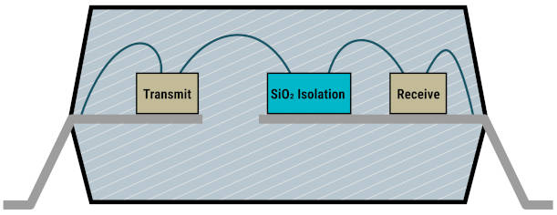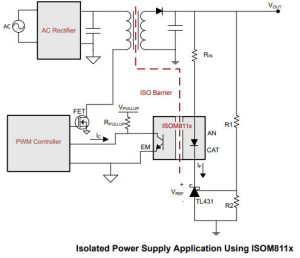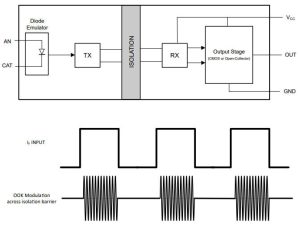
Called ‘opto-emulators’, both analogue and digital versions replace the LED and photo-diode or photo-transistor within a conventional opto-isolator with an SiO2 barrier across which the a modulated version of the input signal is passed – probably magnetically (Electronics Weekly has requested clarification).
The barrier is at least 17μm of oxide, which TI rates at ~500Vrms/µm, compared with ~1Vrms/µm for air, ~20Vrms/µm for epoxy and ~100Vrms/µm for silica-filled package moulding compound.
Isolation is rated at 3.75kVrms (10kV surge) for operation at 500Vrms and 707V peak. CMTI (common-mode transient immunity is a respectable ±125kV/µs.
Opto-isolators tend to have limited temperature range and, along with electrolytic capacitors, the parts most likely to fail first in power supplies.
For the opto-emulators, TI is promising operation over -55°C to +125°C (-40 to +125°C for the digital version) and “significant reliability and performance advantages compared to opto-couplers. Since there is no ageing effect or temperature variation to compensate for, the emulated diode-input stage consumes less power than opto-couplers”.
The company has made these devices electrically very similar to the opto-coupled parts they are intended to replace – the input structures behave much like an LED, and the output structures behave much like a bipolar transistor: “Opto-emulators are pin-to-pin compatible with the industry’s most popular opto-couplers, facilitating seamless integration into existing designs and providing equivalent input and output signal behaviour.”

Just like opto-isolators, ISOM811x devices come in different CTR (current transfer ratio at 5mA in 5Vout) variants:
- ISOM8110, ISOM8115: 100 to 155%
- ISOM8111, ISOM8116: 150 to 230%
- ISOM8112, ISOM8117: 255 to 380%
- ISOM8113, ISOM8118: 375 to 560%
The first device in each entry above emulates a single LED at its input, and the second emulates a pair of anti-parallel LEDs for bi-directional dc inputs.
Typical rise time is 3.2μs with 10V output supply and 100Ω load, with 50pF output capacitance and the output transistor driven to sink 2mA. Fall time is 4μs.
Input structure voltage drop is typically 1.2V at 5mA driv current (1.4V max, or 1.5V max for bi-directional version). Abs max input is 50mA.
Despite not needing an external output-side power supply, output saturation is 300mV with 1mA flowing through the transistor and 20mA current into the input side.
They come in four-pin SOIC packages, 2.65mm high with a 7 x 3.5mm footprint and 5mm creepage. The company is seeking: 3.75kVrms UL 1577 recognition, DIN EN IEC 60747-17 (VDE 0884-17) conformity per VDE and certification to IEC 62368-1, IEC 61010-1 and CQC GB 4943.1.

- ISOM8710 has a totem pole CMOS output
- ISOM8711 has an open-collector output

performance with increasing temperature, forward current and device age.”
Data can be carried at up to 25Mbit/s, and maximums, said TI, are 52ns propagation delay (6mA in), 17ns pulse width distortion and 15ns propogation delay skew.
At the front, the input structure voltage drop is between 1.3 and 1.8V at the recommended 6mA operating current.
Packaging is identical to the analogue version, except for a fifth pin between the two output pins, and the recognitions sought by the company are the same as the analogue version.

Find the digital ISOM8710 product page here, and the open-collector ISOM8711 here


