
“The IC’s designed to extend the life of a typical non-rechargeable lithium coin cell battery while also increasing peak output current by up to 25x compared to what a typical coin cell can deliver without a battery booster,” claimed the company. It makes “coin cells a viable power source for applications which could previously only operate from AA or AAA batteries”.
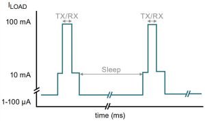
Wireless transceivers result in bursty load characteristics
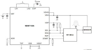
The IC is the NBM7100, which comes in A and B versions – more of this later.
NBM5100 is a similar related IC, intended to work with 3.6V
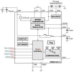
A difference is that the NBM5100 (right) is designed to use a pair of super capacitors (47μF – 470mF, up to 5.5V total) as a local energy storye from which to supply current pulses, while the NBM7100 (below and top) uses a single 4.7 – 470μF capacitor, which it can charge up to 11V.
Both 7100 and 5100 ICs are rated for batteries across 2.4 to 3.6V, including LiMnO2 coin cells and lithium thionyl chloride (Li-SOCl2) batteries.
The ICs have two dc-dc conversion stages:
The first dc-dc is a boost which trickle-charges the capacitive store from the battery – any battery life extension comes from removing high load pulses from the battery.
Sharing the inductor of the first dc-dc, the second (buck) dc-dc is pulse-capable and supplies the bursty output load (nominally the transmitter) from the capacitive store with up to 200mA (150mA for 5100 ICs). Its output can be programmed between 1.8 and 3.6V.
The second dc-dc has an auxiliary output (VDP in diagram) which can provide up to 5mA. “It provides power to ‘always-on’ system loads, for example the host microcontroller core and IO,” said the company.
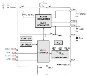 NBM7100 will charge a single 4.7 – 470μF storage capacitor up to 11V
“The intelligent learning algorithm monitors the energy used during repetitive load pulse cycles and optimizes first stage dc-dc conversion to minimise the residual charge in the storage capacitor,” said Nexperia. “When not performing an energy conversion cycle, these devices consume less than 50nA.”
The difference between ..A and ..B versions of the ICs is that A versions have an I2C interface to a host microcontroller and B versions use SPI.
| Part | Bus | Auto Start |
Max store voltage |
Cap balance |
Max load |
| NBM5100A | I2C | Yes | 5.5V | yes | 150mA |
| NBM5100B | SPI | No | 5.5V | yes | 150mA |
| NBM7100A | I2C | Yes | 11V | no | 200mA |
| NBM7100B | SPI | No | 11V | no | 200mA |
An important subtlety is that the second dc-dc converter does not need to operate, as internal switches allow the system to sit in stand-by with the outputs connected directly to the unregulated battery – not via the dc-dc converters.
The store can still be filled by the first dc-dc while the second dc-dc is standing-by, and how the first dc-dc behaves to charge the store is set via serial bus to one of two operating modes: ‘continuous’ or ‘on-demand’. I2C (..A) types get a third mode called ‘auto’.
Continuous mode is intended for loads which need instant current – store voltage is monitored continuously and the store topped up automatically to keep it ready. To switch the output pin from battery (stand-by) to high-current dc-dc output and back, the host has to write to a register.
On-demand mode is applicable to low-duty-cycle applications and maximises battery life – the store capacitance is only charged briefly when instructed to over the bus, and is not recharged until the next charge instruction. The output pin is automatically switched from battery (stand-by) to high-current dc-dc once the store is charged, and a register write is needed to switch it back.
Auto mode is similar to ‘on-demand’ mode, but is initiated by a pulse on the ICs’s ‘start’ pin. If the pulse is short, the chip switched back to stand-by once the load drops below a programmable current threshold. If the pulse is long, the second dc-dc goes back to stand-by at the end of the start pulse.
Both devices are specified over -40 to 85°C and come in 2.5 x 3.5 x 0.85mm DHVQFN16 packaging.
The words above describe only a fraction of what there ICs can do – the data sheets are well worth a brows if coin-cell power interest you.
All four devices are linked form here, and the data sheets are here: NBM7100A/B and NBM5100A/B


