More recently, physics-based reliability prediction has related failure rates of electronic assemblies to the magnitude of temperature change over an operational cycle (power-on, power-off, power-on…) and rate of temperature change, both of which are influenced by steady-state operating temperature.
Electronics failures are often attributed to solder joint fatigue at the package-board interconnect. In some applications, like computing, where performance is key, temperature adversely affects speed. In other cases, components have to run at very similar temperatures to avoid timing issues. High temperatures can cause operational issues, such as latchup. Whether the intention is to increase reliability, improve performance, or avoid problems during operation, accurate prediction of component temperatures helps thermal designers achieve their goals.
Maximize certainty in component temperature prediction
Reliable, accurate prediction of component temperatures allows designers to understand how close the design values come to the maximum allowable* temperature. Here are five tips for achieving high-fidelity component temperature prediction across the design flow and gaining increased confidence in your final simulation results.
Tip 1: Model key components explicitly
To accurately predict a key component’s temperature, the component should be modeled explicitly as part of the thermal simulation. However, not all components need to be modeled, and it is often impractical to do so. Small components with a low power density that are not particularly thermally sensitive can be regarded as thermally benign and do not need to be represented discretely. Heat from these components can be added as a background heat source applied over the whole board or as a footprint heat source on the board. Electronics cooling simulation software should provide filtering options to do this automatically in late design when the populated board layout is imported from the EDA system.
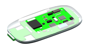
Figure 1 Thermal model of an insulin pump, with components modeled in different levels of detail
Larger components may disrupt the airflow, requiring them to be represented directly as 3D objects. One class of component that can fall into this category is electrolytic capacitors, used, for example, in power supplies. These are thermally sensitive, with a low maximum allowable temperature. Modeling electrolytic capacitors explicitly can help ensure their maximum temperature is not exceeded.
Large, high-power components and components with high power density will need to be modeled discretely, as their thermal management and influence on neighboring components are important to the overall thermal design of the product.
Tip 2: Use good power estimates
As noted above, part of the decision regarding whether it is necessary to represent a component directly depends on its power density, which is the component power divided by its footprint area.
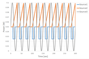
It is worth re-checking decisions about which components to model discretely as the design evolves and more information becomes available. In early design, it may only be possible to use the maximum rated power for the component instead of estimating the likely power consumption. Power budgets for individual components and the board as a whole can change over the course of the design, so these need to be re-checked regularly.
Figure 2 Example power vs. time profile
Tip 3: Use the right package thermal model
The golden rule is to start early and start simple. The mechanical engineer responsible for the thermal integrity of the product should aim to provide as much useful feedback as possible to the electronic engineers to guide the design about the thermal impact of their choices, especially during early design.
From the mechanical engineer’s perspective, at the PCB level, this entails helping with package selection and the best positioning of components to utilize system airflow for cooling. Inevitably, both layout and package selection are driven primarily by a combination of electronic performance and cost considerations. Still, the consequences of those choices on thermal performance should be made as clear as possible, as temperature and cooling also affect performance and cost. The choice of component thermal model depends on several factors.
In early design, before the board is routed or the number of layers in the board is known, accurate component temperature prediction is simply not possible, so a thermally sophisticated model of the component is not called for. Later in the design, when the PCB model can be refined, the component thermal model should also be refined. Choices about the most appropriate component thermal model are iterative, as components predicted to be hot* self-indicate the need to refine the component’s thermal model and perhaps consider a component-specific thermal management solution. The board design can form part of that thermal management solution, for example, using thermal vias to conduct heat to a buried ground plane.
Tip 4: Use compact thermal models from early design
It’s important to model components accurately and use a 3D representation of the component in the thermal design before package selection. 2-Resistor and DELPHI compact thermal models were introduced. Here, we discuss in more detail the predictive accuracy of these and other thermal models.
2-Resistor Models
As noted, a 2-Resistor compact thermal model (CTM) is the lowest fidelity model capable of predicting both case and junction temperatures. One benefit is that it does not require any more mesh than a simple conducting block, so using 2-Resistor models has no negative impact on simulation time. Although this has the lowest computational burden, the worst-case error in junction temperature prediction can be as high as ±30% and varies with both package type and package size. The junction-to-case resistance and junction-to-board resistance thermal metrics this model is based on are measured under standardized conditions.
The JEDEC Standard JESD15-3 requires the junction-to-board resistance to be measured on a 2s2p board with continuous power and ground planes. The junction-to-case resistance is measured by pressing the top of the package against a cold plate. As a result, the predictive accuracy of the 2-Resitor model is higher the more closely the application resembles the test conditions.
For the junction-to-case resistance, the application environment that most closely corresponds to the test environment is when the component has a heatsink covering the whole package surface. For this reason 2-Resistor models can be used to initially assess the size of heatsink required.
Note that the top surface of a 2-Resistor model is an isothermal node representing the case so that the base of the heatsink will be held close to isothermal. A 2-Resistor model can therefore be used to determine the number of fins, fin thickness, and fin height needed to reduce the air-side thermal resistance of the heatsink, but not the base thickness needed to adequately spread the heat to ensure that heat passing to the outer fins is not overly restricted.
RC-Ladder Models
For packages that have a single heat flow path, such as LEDs and TO-style packages, there is a JEDEC standard approach 3 for measuring a thermal resistor-capacitor model of the heat flow path from the junction down to the package tab. Note that this method does not directly provide thermal resistance to the exposed top surface of the package. However, provided this can be estimated by some means, Simcenter Micred T3STER hardware can be used to create an RC-ladder thermal model that takes this into account.
Simcenter Micred T3STER is the industry-leading solution for measuring packaged ICs to create these thermal models, which can be used directly as a Network Assembly in Simcenter Flotherm. Unlike 2-Resistor models, which only contain thermal resistors, these models include thermal capacitors and can be used for transient simulations. These models can give excellent results when the application environment is close to that of the test cold plate environment, e.g., when the package is soldered to an MCPCB or a copper pad on a high-conductivity board.
DELPHI Models
DELPHI models are so-named as they originated from the DELPHI Project coordinated by Flomerics Ltd. in the late 1990s. These models have partitioned top and bottom surfaces, with a matrix of thermal resistors to connect these surfaces to the junction and/or to one another. These additional internal thermal resistors allow the heat flow through these paths within the package to adjust depending on the boundary conditions, and in many applications, the model will predict the junction temperature accuracy to well within ±10%, being a worst-case figure. In general, DELPHI models are adequate for detailed thermal design work of all but the most thermally-critical packages, stacked or 3D ICs, or where additional information is needed from the simulation, e.g., the temperature distribution on the die surface. Like 2-Resistor models they also only contain resistors, so can only be used for steady-state simulation.
Detailed Models
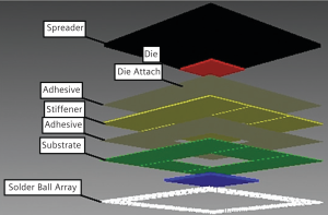
Detailed models are thermal models that discretely model all the thermally relevant features of the package internals. Note that these models often contain some degree of approximation, as features such as individual bond wires and solder balls are often lumped together. However, such models aim to allow the temperature distribution within the package to be accurately represented. If the geometry and material properties are correct, such models offer the highest fidelity.
Figure 3 Detailed thermal model of a chip package
Components that require specific thermal management solutions, such as a heatsink, fansink, or thermal pad should be modeled in detail to correctly optimize the cooling solution. For example, in the case of a heat sink, it has long been known that the temperature distribution in the package influences the temperature distribution in the heatsink base and vice versa. Consequently, detailed package thermal models are recommended for such purposes.
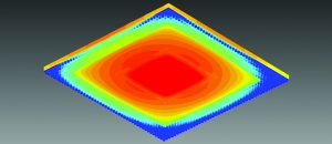
Another advantage of detailed models is that they allow the temperature of the solder interconnect to be predicted. Thermomechanical shear, coupled with temperature change, is the primary stressor affecting solder joint life.
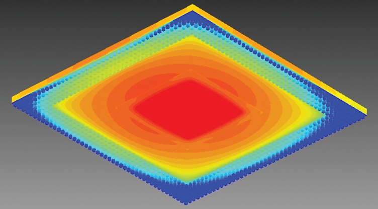
Figure 4 Temperature distribution on underside of a BGA package showing individual soler balls
BCI-ROMs
A recent advance in predicting component temperatures is through the use of reduced order models, or ROMs. ROMs can now be created independently of their boundary conditions (BCI) rather than specific for a given thermal environment. That means that BCI-ROMs can be created by package vendors, independent of their thermal environment, and provided to end users for use in simulating a specific thermal environment. They are available in a variety of formats, such as raw matrices, SPICE, VHDL-AMS, and FMU. There are now a range of authoring options for BCI-ROMs within Simcenter.
BCI-ROMs have other very desirable characteristics:
- They are highly accurate, with the accuracy defined as part of the creation process (typically > 98%)
- Support multiple heat sources
- Support all transient timescales
- Hide sensitive IP as the internal geometry of the parent detailed model from which they are derived can not be reverse-engineered from the ROM
- Report the appropriate junction temperature defined by the vendor without the vendor having to reveal where within the model that is.
- Solve orders of magnitude faster than detailed models
A major advantage of this is that they can be included in circuit simulators, like Xpedition AMS and PartQuest Explore, allowing them to be ‘temperature aware,’ which is key to getting accurate power estimates in early design.
Use of BCI-ROMs within 3D CFD simulators has the potential to be a game-changer in the supply chain for package thermal models, and BCI-ROMs can also be created for whole boards.
Tip 5: Create your models as required
In practice, the choice of thermal model may largely depend on what is available from the vendor. Even today, we find vendors may only supply information in the form of a datasheet, e.g., as a PDF, and these may not contain the information necessary for even basic thermal design. For example, the data sheet may contain only a junction-to-ambient thermal resistance, which can’t be used for design, and only performance comparison. JEDEC has published JEP1817, a standard file format for thermal simulation data exchange. It is XML-based, using ECXML developed by Siemens, short for ‘electronics cooling extensible mark-up language’.
We hope that these tips have started your journey to improve component temperature predictions. For an additional five tips, please download this free whitepaper.
Author
Dr. John Parry, Simcenter Industry Director, Electronics & Semiconductor, Siemens Digital Industries Software

