
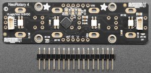
It comes in the form of a PCB with four footprints that accept one of the most common rotary encoder forms (Bournes PEC11 horizontal style), allowing the user to pick devices with the appropriate step-count per revolution, with or without a push switch.
“The [pre-soldered] on-board microcontroller is programmed with our ‘seesaw’ firmware, and will track all pulses and pins for you and then save the incremental value for querying at any time over I2C,” according to the company. “You can use our Arduino library to control and read data with any compatible microcontroller. We also have CircuitPython-Python code for use with computers or single-board Linux boards.”
Power and data passes through 1mm pitch 4pin JST SH connectors – using SparkFun’s ‘Qwicc’ pinout for which cables are available (which Adafruit brands ‘Stemma QT’), and there is a pair of them to allow other compatible sensor boards to be daisy-chained. “Stemma QT devices keep the level shifting/regulator, so you can use Stemma QT with Grove, Gravity, Stemma and Qwiic controllers at any voltage range”, said Adafruit.
Alternatively, power (3 to 5V) and data 3 or 5V logic) can be connected to six 0.1inch header-compatible pads. “The interrupt pin can be configured to pulse low whenever rotation or push-buttoning is detected so you do not have to spam-read the I2C port to detect motion,” said Adafruit.
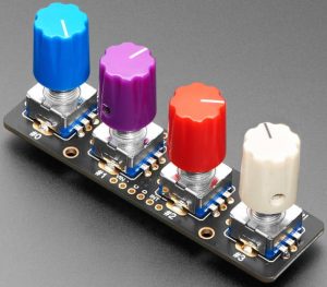
Controlled over the same I2C, pre-installed multi-coloured LEDs under each encoder footprint allow translucent knobs to be back-lit, but only if transparent-shaft encoders have been installed.
Other LEDs indicate power and interrupt, and three jumpers allow one of eight I2C addresses (0x49 to 0x51) to be selected.
Adafruit I2C quad rotary encoder breakout board product page
Adafruit Seesaw library in Github – and Python version


