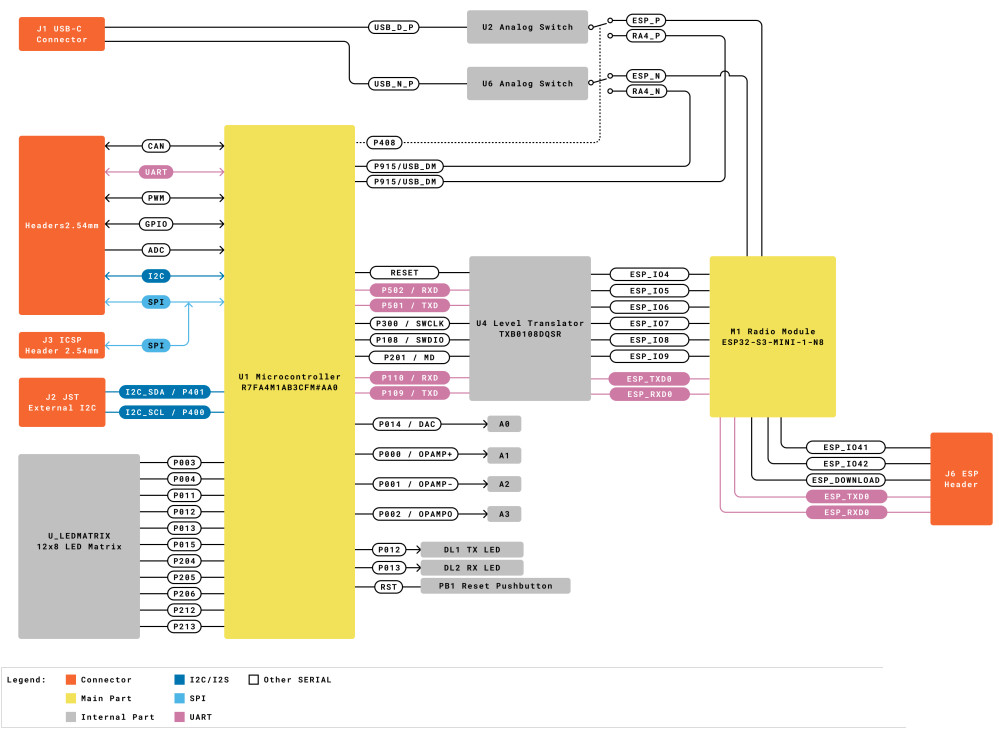
5V IO
6 – 24Vin (barrel jack)
5Vin (USB-C)
14x digital GPIOs, D0-D13
(6x PWM: D3,D5,D6,D9,D10,D11)
6x analogue (14bit ADC) input, A0-A5
(A0 pin also true analogue via 12bit DAC)
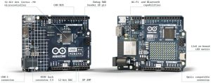
48MHz Renesas RA4M1 with Arm Cortex-M4 and FPU
256kbyte flash
32kbyte ram
8kbyte eeprom
1x UART (D0, D1)
1x SPI (D10-D13, ICSP header)
1x I2C (A4, A5, SDA, SCL)
1x CAN (D4, D5, needs external transceiver)
USB 2.0 full-speed, able to simulate a mouse or keyboard to a host PC.
Op-amp
Capacitive touch sensing
Memory protection unit
(not on ‘Minima’)
Wi-Fi 2.4GHz 802.11b/g/n up to 150Mbit/s
Bluetooth 5
Built-in antenna
12 x 8 LED matrix
Qwicc-style connector for 3V3 I2C – additional channel from Renesas MCU
Connector to add external battery to real-time clock (RTC) inside Renesas MCU (MCU RTC power pad held to 5V rail on Minima version)
Secondary (wireless) processor:
3.3V Espressif ESP32-S3-MINI-1-N8 module
(dual-core 32bit LX7, 3V3 from local 5V via LDO)
384kbyte rom
512kbyte ram
40MHz crystal oscillator
Dedicated programming header
No access to ‘Arduino’ board-edge IO pins
Two big differences under the hood
One big difference between the two boards is that the Renesas MCU on ‘Minima’ is programmed directly over USB while, on the ‘WIFI’ version, the main Renesas MCU is programmed via ESP32-S3 (Wi-Fi) processor.
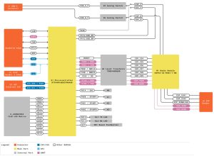
To achieve this, the USB bus is connected directly to ESP32-S3 – although an on-board jumper allows the USB to be switched over to the Renesas MCU.
A second difference is that Minima has the Renesas MCU debug bought out to connector called ‘SWD’ for connection to an external debugger, while on the WIFI version the Renesas MCU debug port is taken to the ESP32. “UNO R4 WiFi includes an error-catching mechanism that detects run-time crashes and provides detailed explanations and hints about the code line causing the crash,” according to Arduino.
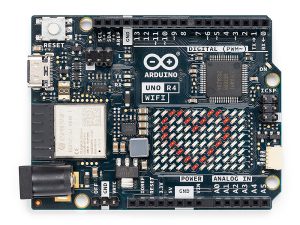
The on-board 12 x 8 (96pixel) matrix of red LEDs is Charlieplexed for pixel-level addressing.
Arduino_LED_Matrix API is available for programming and control, and “we have developed a graphic tool designed to help makers create and export their own animations”, according to Arduino.


