 Micsig Technology is aiming at mains and high-voltage GaN power supply development with a series of optical fibre isolated oscilloscope probes, with bandwidths up to 1GHz and risetimes down to ≤350ps.
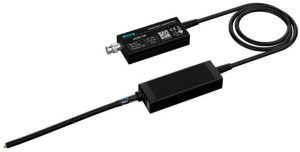
This kind of probe has no electrically-conductive path between probe tip and scope.
Instead, the scope end of the probe and the probe’s head are linked by optical fibres, along which an analogue optical representation of the signal is passed down to the scope-end, while power is passed up to the head, by a laser in this case.
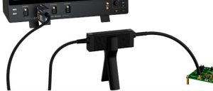
A bipod supplied with the probe reduces head capacitance to ground
As a result of electrically-insulated signal and power transmission, maximum common-mode withstanding is 60kV.
An amplifier at the head presents 1MΩ in parallel with 10pF to the probe tip via an SMA connector, and probe tips between 10x and 2,000x are available to connect to the signal of interest. Capacitance at the signal interface is ~3pF, and even ~1pF in the x2,000 case (performance tables below).
“Device like GaN and SiC can switch high voltages in a few nanoseconds, containing very high-energy high-frequency harmonics,” according to the company, which is branding the probes SigOfit. “SigOfit probe delivers high common mode rejection ratio: up to 112dB at 100MHz and over 100dB at 500MHz.”
These CMMR figures are at the SMA connector, and reduce somewhat (table below) when the tips are installed.
![]() The various probe tips (right) give a possible sensed signal range from ±1.25V full-scale to ±2.5kV, and dc gain accuracy ±1% – with a 1.41mVrms noise floor.
The various probe tips (right) give a possible sensed signal range from ±1.25V full-scale to ±2.5kV, and dc gain accuracy ±1% – with a 1.41mVrms noise floor.
The probe tips terminate in a coaxial connector and, for maximum signal fidelity, this should be paired with a matching coaxial socket on the board-under-test.
With no dc reference transferred from tip to head, offset drift is possible. Drift is said to be <500μV after warm-up, and a push button at the scope and of the probe initiates an auto-calibration to remove any zero offset in less than a second.
50Ω is expected at the scopes BNC input, and the scope end box of the probe (which has an internal fan for cooling) is powered from a separate power supply.
A buzzer sounds if the probe over-heats or the input voltage is out of range.
Specifications
| MOIP01P | MOIP02P | MOIP03P | MOIP05P | MOIP08P | MOIP10P | |
|---|---|---|---|---|---|---|
| Bandwidth | 100MHz | 200MHz | 350MHz | 500MHz | 800MHz | 1GHz |
| Rise time | ≤3.5ns | ≤1.75ns | ≤1ns | ≤700ps | ≤438ps | ≤350ps |
| SMA input impedance | 1MΩ || 10pF | |||||
| Output | ±2.5V | ±1.25V | ||||
| Differential range |
1x:±2.5V 10x:±25V 20x:±50V 500x:±1,250V 1,000x:±2,500V |
1x:±1.25V 20x:±25V 50x: ±62.5V 1,000x:±1,250V 2,000x:±2,500V |
||||
| Noise | <1.41mVrms | |||||
| Propagation Delay | 15.4ns (2m cable) | |||||
| Power Supply | USB Type-C 5Vdc | |||||
| DC Gain Accuracy | 1% | |||||
| Common mode Range | 60kVpk | |||||
| Cable length | 2m (custom available) | |||||
| tip type | atten | input impedance |
| SMA | 1x | 1MΩ || 10pF |
| OP10 | 10x | 10MΩ || 3.0pF |
| OP20 | 20x | 9.47MΩ || 2.8pF |
| OP50 | 50x | 9.47MΩ || 2.8pF |
| OP500 | 500x | 12.27MΩ || 2.6pF |
| OP1000 | 1,000x | 12.28MΩ || 2.6pF |
| OP2000 | 2,000x | 30MΩ || 1pF |
| Common mode rejection ratio | ||||||||
| Probe Tip | DC | 1MHz | 100MHz | 200MHz | 350MHz | 500MHz | 800MHz | 1GHz |
| SMA | 160dB | 152dB | 112dB | 106dB | 102dB | 100dB | 94dB | 92dB |
| OP10 | 160dB | 120dB | 96dB | 92dB | 90dB | 86dB | 84dB | 82dB |
| OP20 | 160dB | 120dB | 92dB | 90dB | 86dB | 84dB | 82dB | 80dB |
| OP50 | 160dB | 115dB | 86dB | 82dB | 80dB | 78dB | 75dB | 74dB |
| OP500 | 160dB | 96dB | 56dB | 48dB | 40dB | 32dB | 28dB | 26dB |
| OP1000 | 160dB | 90dB | 50dB | 42dB | 34dB | 26dB | 22dB | 20dB |
| OP2000 | 160dB | 90dB | 50dB | 42dB | 34dB | 26dB | 22dB | 20dB |
The fibre-isolated scope probe web page can be found here